
Position Tracker
August 2015
Overview
This project is a proof of concept finger position tracker to be used with a touchscreen that gives haptic feedback. Traditional methods of finger tracking with touchscreens face challenges of reliability and accuracy when implementing haptic feedback. This project explores bringing a mixture of technologies together to overcome these obstacles.
Below is the working demo of the finger position tracker. The laser scans and locates the edge of a finger and tracks the position using feedback from a solar cell sensor and Hall effect sensor.
There were many design considerations in what technologies would be accurate, fast, reliable, and scalable. Because of the particular application, capacitative or resistive touch wasn’t an option, and design requirements wanted to avoid any overhead or underneath cameras. The current prototype uses a laser and mirror, a voice coil from a computer hard drive, a Hall effect sensor and magnet, a solar cell, and a PIC32 microcontroller. The voicecoil has a mirror and magnet mounted on top of it, with a Hall effect sensor over top to act as the feedback on the position, as pictured below.
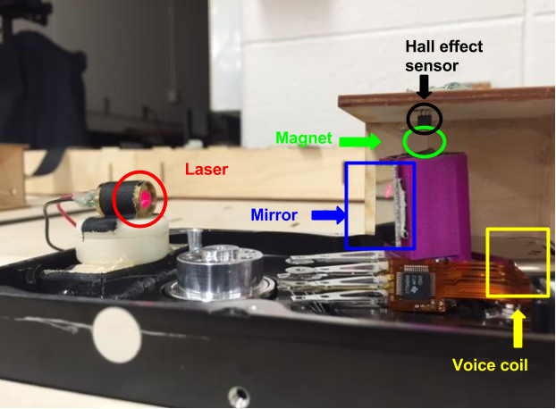
The laser hits the mirror and is redirected at a solar cell which outputs a signal that is processed to determine whether the laser is hitting a finger or not based on the solar cell output.
Project outline
The main components of the project were broken down into five parts:
- Controlling the voice coil
- Implementing the Hall effect sensor
- Converting sensor data to position
- Implementing the solar cell
- Designing the controls
Step by step
- Controlling the voice coil
- I disassembled an old computer hard drive to gain access to the voice coil inside. The theory behind a voice coil is a coil inside a magnetic field. Depending on the current direction on the coil, the arm moves to one side or the other. And depending on the intensity of the current, the speed will be faster or slower. I used an H-Bridge to control the current direction on the coil and pulse width modulation (PWM) to control the speed, as the microcontroller isn’t capable of variable analog output.
- Implementing the Hall effect sensor
-
Once I was able to control the direction and speed of the voice coil, the next step was to accurately determine the position of the voice coil. I mounted a magnet and Hall effect sensor above the voice coil. When a Hall effect sensor is subjected to a magnetic field, it responds with an output voltage proportional to the magnetic field strength. In this application, the sensor is in a fixed position while the magnet is fixed to the voice coil and rotates.
-
The microcontroller has an analog-to-digital converter (ADC) that can sample an analog input (Hall effect sensor) with 10-bits of resolution, or 1024 different voltage values over 0-3.3 volts. The Hall effect output was connected to the microcontroller ADC to assign a value to the position. However, since the Hall effect output range was only ~1V, in order to utilize a larger portion of the 0-3.3V, or 1024 bits of resolution, I used an op-amp to amplify the signal. Having better resolution allows for better position accuracy of the voice coil.
-
- Converting sensor data to position
- After being able to control the voice coil and its position, a prototype of a grid was made to help calibrate the conversion of Hall effect output to real world coordinates. Several tests were run to accurately gather the Hall effect reading at both edges of the sensing area. The sensing area is a known value, so we can calculate the the inches per bit of resolution to determine our accuracy.
- Implementing the solar cell
- Solar cells rely on the photoelectric effect, the ability of matter to emit electrons when a light is shone on it. In this application, I measured the output voltage from the solar cell. When shining a light or laser at the solar cell, there is a rise in the output voltage compared to without. The microcontroller being used has limitations on the current and voltage it can handle. In order to keep the current within range, solar cells were connected in series. In series, voltage is additive and current is constant. Since voltage is additive, the solar cell output would be too high for the microcontroller.
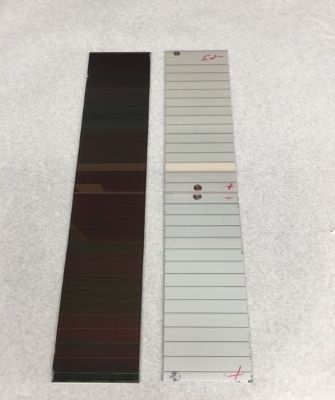
Below is the front (left) and back (right) of a solar cell. On the right, the + and - connections are labeled to show how they will be connected in series.
In order to reduce the output voltage further, the amount of exposed area of the solar cell was reduced to focus on where the laser would hit by covering with a black tape. In addition to limiting the exposed area, a filter film was applied to eliminate light outside of the red spectrum which is the color of the laser.
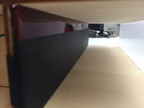
Below is the completed solar cell with the light filter and light blocking tape.
The next step is to create a housing to reduce some of the ambient light sources. It was determined that a light diffuser would improve performance of the solar cell output as it only needs to detect a new light source and not be concerned with the intensity at one location. And lastly, a diode was used as protection to ensure the maximum voltage into the microcontroller was not exceeded.
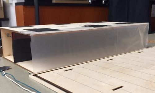
Pictured below is the housing that provides overhead coverage from light and a light diffuser over the front.
- Designing the controls
-
Everything is now set up to implement the controls and feedback! The method being used connects the position feedback and the solar cell output to determine if the laser is hitting a finger and the position of the finger.
-
Initial locating of the finger - the solar cell output is being converted by the ADC at a fixed frequency. Every time it samples, the new sample is compared to the previous sample. The first step the system does is scan the laser across the area of interest. If there is a large difference in the value, then it is determined that a finger is either blocking the solar cell or was previously blocking the solar cell. This signals the edge of a finger.
-
Staying with the finger - If the solar cell output went from high to low, this indicates going from solar cell to finger. If the cell output went from low to high, this indicates moving from the finger onto the solar cell. Using this logic lets the user know when a finger is located, what edge is found. The laser continues moving in the direction it was going after it finds the first edge. Once the output of the solar cell goes from low to high, the second edge of the finger has be located. After the second edge is found, the laser will change direction and repeat the process to stay with the finger.
-
Relocating the finger - in the case that a finger is removed from the area of interest, the same method is used as initially finding the finger to scan the area looking for a discernible difference in the solar cell output.
-
Position calculation - When the edge of a finger is found, the position reading from the Hall effect sensor is stored and converted into cartesian coordinates. Since the laser scans for both edges of the finger, using the two locations of the edges allow for calculation of the centroid for a more accurate position.
-
Component information
Microcontrollers: a PIC32MX795F512L was used along with a breakout board for this project. Microcontrollers are typically used for embedded applications and automatically controlled products and devices. More information can be found here.
H-Bridge: is a commonly used circuit in motor control containing switching elements to allow a current to be applied giving motor control in either forward or reverse. More information can be found here
Hall effect sensors: can measure the strength of a magnetic field. When it is subjected to a magnetic field, it responds with an output voltage proportional to the magnetic field strength. Common applications include position sensing, DC current transformers, and level indicators. More information can be found here
Op amps: are a type of differential amplifier that depending on external feedback elements can perform a variety of operations. More information can be found here
Diodes: are components that are used to control the direction of current flow. Diodes have low resistance to current in one direction and high resistance in the other direction. More information can be found here
Further resources
PWM - is a technique used mainly to control the power supply from a DC source. Since a DC power supply can only give 1 output voltage, PWM will switch a power source on and off allowing the user to create an average voltage by specifying the duty cycle of the signal.
ADC - is a feature that converts an analog voltage to a digital number. This is very useful in devices that operate in the digital world.